Understanding Shell Elements and Thickness Assignment

Hello,
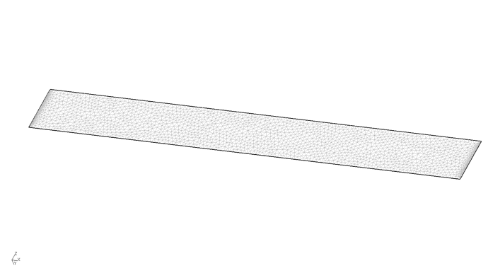
In an attempt to understand how shell elements work in CalculiX, I set up a shell beam and set different thicknesses namely, 0.1, 0.5, 1 and 2. All of them are subject to a CLOAD of 10N in the negative y direction at one end.

I assumed that the thickness value would not impact the resulting displacements or stresses however, the values are very different and I do not think this is accurate.
I have attached a link to my 0.5 thickness case for reference. Where exactly have I gone wrong in the case set up? How may I be able to fix this?
https://myunt-my.sharepoint.com/personal/mishalraza_my_unt_edu/Documents/Attachments/shell_0.5.zip

Would appreciate any help.

What about your handcalculation for displacement of your beam?

Is it bending ? It’s hard to say based on the picture since the geometry seems to be misaligned with axes of global coordinate system (or maybe it’s just a matter of unfortunate view orientation).

Anyway, why would you expect no difference when the thickness of the beam is changed ? Then its stiffness will also change and stresses depend on the cross-section dimensions as well. Analytical calculations should clarify this.

Please try sharing the file again, this link leads to login page.

a concentrated load of 10N is applied on the end with 50 nodes so the value for displacement is supposed to be for 500N right?
I got the displacement as 4 but the simulation gives 1.48 when I use:
Max Disp = PL/3EI

you can check the result of your boudary with:

*NODE PRINT,NSET=Nsbound_01,totals=only
RF

working with bending properties it is recommended to work with
quadrangle or hexahedra elements

It is not bending. Just a bad view.


Is this better?

How do you suggest I upload? I am unable to upload a zip folder.

I expect no difference because I thought the purpose of assigning a thickness to a shell was just to create a virtual volume that Calculix can use to solve.

This is my current .inp file:

*INCLUDE, INPUT=all.msh
*INCLUDE, INPUT=fix.nam
*INCLUDE, INPUT=load.nam
*MATERIAL, Name=EL
*ELASTIC
4000000, 0.3
*DENSITY
3000
*SHELL SECTION, Elset=Eall, Material=EL, OFFSET=0.5
0.1
*STEP, INC=1000000
*DYNAMIC, ALPHA=0.0, DIRECT
1.E-2, 5.0
*BOUNDARY
Nfix, 1,3,0
*CLOAD
Nload, 2, -10.0
*NODE FILE
U
*EL FILE
S, E
*END STEP

You can use hosting services like Google Drive, Dropbox or even WeTransfer. Just make sure that everyone can download the files after clicking the link.

Shell elements represent thin solids and their thickness is important for calculations. Just like the cross-section shape and dimensions in the case of beam elements.

I tried this @dichtstoff
How should I share the output file?

maybe these can work:

*INCLUDE, INPUT=all.msh
*INCLUDE, INPUT=fix.nam
*INCLUDE, INPUT=load.nam
*MATERIAL, Name=EL
*ELASTIC
4000000, 0.3
*DENSITY
3000
*SHELL SECTION, Elset=Eall, Material=EL
0.1
*STEP
*STATIC
*BOUNDARY
Nfix, 1,6,0
*CLOAD
Nload, 2, -10.0
*NODE PRINT,NSET=Nfix,totals=only
RF
*NODE FILE
U
*EL FILE , OUTPUT=2D
S, E
*END STEP

if you double thickness, displacement should be half
and please check the definition of a beam with dimension

Is this working?

Yes, I downloaded the files.

The structure is clearly subjected to bending. Each node on the loaded edge receives 10 N and there are 50 nodes on that edge so the total load should be 500 N.

What unit system are you using ? Are dimensions given in meters ?

Why are you using dynamic step ?

According to analytical calculations assuming linear statics, the maximum values should be y=4 and σ=120000.

Try solving this with solid elements.

Thank you for checking. I ran this case with solid elements too but the results were different.

*NODE, NSET=Nall
1,0.000000000000e+00,0.000000000000e+00,0.000000000000e+00
2,1.500000000000e+01,0.000000000000e+00,0.000000000000e+00
3,1.500000000000e+01,1.500000000000e+01,0.000000000000e+00
4,0.000000000000e+00,1.500000000000e+01,0.000000000000e+00
5,1.500000000000e+01,3.000000000000e+01,0.000000000000e+00
6,0.000000000000e+00,3.000000000000e+01,0.000000000000e+00
7,1.500000000000e+01,4.500000000000e+01,0.000000000000e+00
8,0.000000000000e+00,4.500000000000e+01,0.000000000000e+00
9,1.500000000000e+01,6.000000000000e+01,0.000000000000e+00
10,0.000000000000e+00,6.000000000000e+01,0.000000000000e+00
11,1.500000000000e+01,7.500000000000e+01,0.000000000000e+00
12,0.000000000000e+00,7.500000000000e+01,0.000000000000e+00
13,1.500000000000e+01,9.000000000000e+01,0.000000000000e+00
14,0.000000000000e+00,9.000000000000e+01,0.000000000000e+00
15,1.500000000000e+01,1.050000000000e+02,0.000000000000e+00
16,0.000000000000e+00,1.050000000000e+02,0.000000000000e+00
17,1.500000000000e+01,1.200000000000e+02,0.000000000000e+00
18,0.000000000000e+00,1.200000000000e+02,0.000000000000e+00
19,3.000000000000e+01,0.000000000000e+00,0.000000000000e+00
20,3.000000000000e+01,1.500000000000e+01,0.000000000000e+00
21,3.000000000000e+01,3.000000000000e+01,0.000000000000e+00
22,3.000000000000e+01,4.500000000000e+01,0.000000000000e+00
23,3.000000000000e+01,6.000000000000e+01,0.000000000000e+00
24,3.000000000000e+01,7.500000000000e+01,0.000000000000e+00
25,3.000000000000e+01,9.000000000000e+01,0.000000000000e+00
26,3.000000000000e+01,1.050000000000e+02,0.000000000000e+00
27,3.000000000000e+01,1.200000000000e+02,0.000000000000e+00

*ELEMENT, TYPE=S4, ELSET=Eall
1, 1, 2, 3, 4
2, 4, 3, 5, 6
3, 6, 5, 7, 8
4, 8, 7, 9, 10
5, 10, 9, 11, 12
6, 12, 11, 13, 14
7, 14, 13, 15, 16
8, 16, 15, 17, 18
9, 2, 19, 20, 3
10, 3, 20, 21, 5
11, 5, 21, 22, 7
12, 7, 22, 23, 9
13, 9, 23, 24, 11
14, 11, 24, 25, 13
15, 13, 25, 26, 15
16, 15, 26, 27, 17

*MATERIAL,NAME=Steel
*ELASTIC
200000,0.3

*SHELL SECTION,ELSET=Eall,MATERIAL=Steel
1

*STEP
*STATIC

*BOUNDARY
1,1,6,0
2,1,6,0
19,1,6,0
*CLOAD
17,1,10000

*NODE FILE, OUTPUT=2D
U,
*EL FILE
S,
*END STEP

these simple inp file works perfect. very simple:

dimension 120x30x1 E=200000 F=10000
f=Fxl^3x12 / 3 / E / t / h^3 = 12.80 CCX = 13.2
Sorry, I just saw this. Will try this now

@dichtstoff, I tried this with 0.5 thickness and I got 3.59 as displacement which is close to theoretical value of 4!
However, is this considered normal? Isn’t the error quite big?
Also, I ran the same case for a solid section but got a displacement value of 6.81. Is this because I now have more nodes in the load NSET? How may I set this up so that I could get the same results as a shell?

Units are SI.
is this stress value, σ=120000, the SXX?

triangle elements are a bit stiffeners than hex or quad elements
you have your load in one node, and not over the hole length,
beam is defined with a less hight and more length, you have opposite
you can use 2-elements or you can calc. with selfweight
i guess it is possible to get the same result with shell elements

Okay @dichtstoff. So, if I get this correctly, I should change the elements I use for the solid right? to get closer results.
Also, what do you mean about the beam? Do you think I could have better dimensions? Like a longer beam? Right now it is 10 units long and 1 x 0.5 cross section.

Also, do you think I could use a DLOAD on the node set to get similar results? I tried generating a distributed file with CGX using the following command:
“send load abq pres 10.0”
however, the .dlo file generated is always empty and I am not sure why.

yes, if you work with bending properties, you should use not triangle elements:
for all elements, shell, solid or 2-D plane elements:
(and from my experience, it makes in no different in ccx, if you use second order elements,
for triangle elements, but you have to test it)

you will find more information if you look for it like these:

1 Like