That’s also my suspicion but switching the master-slave assignment doesn’t help. I wonder if it’s possible to eliminate this issue in some way. In the above case it happens even away from the current contact region and the elements always collapse drastically. So far, only very low stick slope helped me avoid this issue in previous tests (as I’ve mentioned before, 10 is max for that non-refined model). The problem is that it has to be higher to get correct forces.
is Abaqus also produced large residual force at end steps? my understanding is violating equilibrium and i don’t give a trust in results.
my solution. It takes almost 7 hours to run in a 12 cores machine. The link provides results as well (zipped, when unzipped about 1.3GB).
https://drive.google.com/drive/folders/1NmpJML9pvBXknZ3f-1C9Sv1T0dmBN3Bw?usp=sharing
main features: linear elements, changed master-slave, suppression of rigid bodies.
** Surface interactions ++++++++++++++++++++++++++++++++++++
**
*Surface interaction, Name=Surface_Interaction-1
*Surface behavior, Pressure-overclosure=Linear
1000000, 2.86
*Friction
0.3, 100000
*Step, Nlgeom, Inc=1000
*Static, Solver=Pardiso
0.01, 1, 1E-05, 0.01
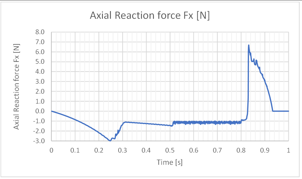
Results: still a bit bumpy and makes “the snake” at some point (only very very lightly) but I think overall behaviour is same as yours, didn’t check yet the loads but as have noticed stick slope is 100000


at t=0.51 elements collapse, but they’re not in contact!!!

and stay like that until the end, I guess the problem is the mesh as well.
Thanks again.
That’s exactly what I’m struggling with now. I can’t find a logical reason why it’s happening or a way to prevent it. I only know that the stick slope can affect this behavior. The forces are good now and only this is still bothering me.
1 Like
I wanted to add some pictures too to this thread. Have gotten the same issues as above mainly because of a coarse mesh and a too big increment size. I got rid of the sharp edges and ran the simulation with smaller increment size.
Which works pretty good.


https://github.com/NorbertHofbauer/Cubit-CalculiX/tree/main/examples/snap_fit
....
**
********************************** M A T E R I A L S ****************************
*MATERIAL, NAME=ABS
*ELASTIC,TYPE=ISO
2.000000e+03,3.940000e-01,0.000000e+00
*DENSITY
1.020000e-09,0.000000e+00
*SPECIFIC HEAT
1.386000e+09,0.000000e+00
*EXPANSION,TYPE=ISO
7.400000e-05,0.000000e+00
*CONDUCTIVITY,TYPE=ISO
2.256000e-01,0.000000e+00

********************************** S E C T I O N S ****************************
*SOLID SECTION, MATERIAL=ABS, ELSET=Block_1
*SOLID SECTION, MATERIAL=ABS, ELSET=Block_2
********************************** C O N S T R A I N T S ****************************
*RIGID BODY, NSET=Nodeset_1, REF NODE=2618, ROT NODE=2619
********************************** S U R F A C E I N T E R A C T I O N S ****************************
*SURFACE INTERACTION,NAME=SurfaceInteraction1
*SURFACE BEHAVIOR,PRESSURE-OVERCLOSURE=LINEAR
8.000000e+04,1.000000e-06,1.000000e-03
*FRICTION
1.000000e-01,4.000000e+04
********************************** C O N T A C T P A I R S ****************************
*CONTACT PAIR, INTERACTION=SurfaceInteraction1, TYPE=SURFACE TO SURFACE
Surface_2,Surface_1
********************************** A M P L I T U D E S ****************************
********************************** I N I T I A L C O N D I T I O N S ****************************
********************************** H B C s ****************************
********************************** S T E P S ****************************
**** STEP 1 NAME: move_1
*STEP,NLGEOM,INC=500
*STATIC,SOLVER=PARDISO,TOTAL TIME AT START=0.000000e+00
1.000000e-05,9.000000e-01,1.000000e-08,1.000000e-02,
*BOUNDARY
Nodeset_2,1,1,0.000000e+00
Nodeset_2,2,2,0.000000e+00
Nodeset_2,3,3,0.000000e+00
*BOUNDARY
Nodeset_3,1,1,9.270000e+00
Nodeset_3,2,2,0.000000e+00
Nodeset_3,3,3,0.000000e+00
*BOUNDARY
Nodeset_4,1,1,0.000000e+00
Nodeset_4,2,2,0.000000e+00
Nodeset_4,3,3,0.000000e+00
*NODE PRINT, NSET=Nodeset_3
U,RF
*NODE FILE
U
*EL FILE
E,S
*CONTACT FILE
CDIS,CSTR,CELS
*END STEP
**** STEP 2 NAME: move_2
*STEP,NLGEOM,INC=500
*STATIC,SOLVER=PARDISO,TOTAL TIME AT START=9.000000e-01
1.000000e-05,1.000000e-01,1.000000e-08,1.000000e-03,
*BOUNDARY
Nodeset_3,1,1,1.030000e+01
Nodeset_3,2,2,0.000000e+00
Nodeset_3,3,3,0.000000e+00
*NODE PRINT, NSET=Nodeset_3
U,RF
*NODE FILE
U
*EL FILE
E,S
*CONTACT FILE
CDIS,CSTR,CELS
*END STEP
1 Like
I have also run it with plain strain (the support is far, and the piece is deep enough to consider this option) rounding very slighly the corner (one node).

The results are equivalent with no breaks at all in the model.
The Contact stiffness to obtain an acceptable maximum clearance has had to be increased to 8000000E6 [Pa]
I have respect friction and correct proportionally the Sticky slope ratio to K/100.
*Surface interaction, Name=Interaction-1
*Surface behavior, Pressure-overclosure=Linear
8000000E6, 1E1
*Friction
0.3, 80000E6
Final Fx=2.99 N
The fact that this has been solvable so easy (just one element in depth) ,that high Sticky Slope is acceptable and the smothness of the run (6 min) makes me reconsider my 3D approach and if there is some issue in my set up or solver.

1 Like


I get this in plane strain with your settings:

It happens right after the beam bounces back to reestablish contact with the block. I’ll play with the settings (especially for the mesh) but I haven’t been able to eliminate this behavior so far. Which type of elements are you using? Unfortunately, my mesh has to include triangles when there are those fillets.
Really clean and sharp transition.
Do you think the problem could be the Wedge elements under shear?
I’m using linear S4R for the master and S8R for the brick so I can get a clean rounded contour.
Thanks, I’ll keep trying.
Could be but I think I had a similar issue with tetras. I’ll keep trying but this behavior is really annoying.
can Abaqus solved with hard contact type?


p.s element type is linear hexahedral (incompatible), sectional force of cantilever hook can be more clear in reporting also.
Yes, this was with the default hard contact and the trick described in the first post - additional node-to-surface contact for the edge. General contact works too but the forces are different (too low).
if i can understand, basically Abaqus can not but some trick does make it work.
btw, is the support recorded is similar (top only) or still using rigid body at whole small block parts as original models?
It didn’t converge with just the surface-to-surface contact pair. But general contact worked straight away. I haven’t tried to further improve the Abaqus model because it worked well enough so I focused on the issue in CalculiX.
The Abaqus model was the same as my initial CalculiX models so with rigid bodies (the whole block included).
for some reason i can not generate reaction force in reference point of rigid block models, but sectional forces history at cantilever hook can be used as comparison.

normal force,

shear force,


So I think we can trace the difficulty to the contact condition not being a typical face-to-face, I’ll try confirming this point changing the part surfaces so there is a little but clear surface contact in ccx. It seems that abaqus resorts to special formulations for this kind of problems.

http://doc.abaqus.its.qmul.ac.uk/English/SIMACAEITNRefMap/simaitn-c-contactgeneralstd.htm
2 Likes
Thank you JuanP74.Let us now your results. It will for sure bring some light and guidance to approach other problems.
That’s the typical scenario for a bolt and the hole edge with the added difficulty that those edges are curved.
By other hand in the clip problem, leading edge passes from belonging to the slave to the master and the required stiffness to sustain the clearance is governed just by an small area of the whole path. Really challenging.
Now I look it twice, it looks too sharp to belong to a rounded corner. Calc_em, are you using the same geometry?
Plain Strain fails with node to surface formulation.
Yes, that’s what I’ve mentioned in the first post:
The geometry used in Abaqus is this one:

I tried with a small fillet on the top right edge of the beam’s tip but it was actually worse so I left the Abaqus model as it was and started changing it in various ways to make it work in CalculiX.
Yes, I’ve tried that too. Unfortunately, two contact of different types can’t be used in CalculiX, unlike in Abaqus.
I was not familiar with those contact technicalities in abaqus, so I hadn’t assimilated the meaning of what you wrote, sorry.