based on the documentation, it seems that CalculiX doesn’t support the no separation contact (in Abaqus it can be defined using *Surface behavior, no separation). But is there another way to model this type of contact in CalculiX ? The documentation for cgx mentions the application of MPC equations in such cases but that’s not what I’m looking for (I want to stay with contact and I don’t use cgx).
The reason why I need to define the no separation contact is that I’m trying to simulate a leaf spring and tie constraints overstiffen the model while standard contact (with possible separation) does not converge (and I think that it will be very hard to converge it in this case).
Hi Calc_em
I have try intercalating layers of an orthotropic material with large stiffness only in the vertical direction and almost cero in the other two an it seems to work.
Very low shear modulus too to allow easy slip of the shells.
Note: Be sure all the element axis are aligned in the same direction.
Thank you, that’s an interesting workaround. To clarify - how did you connect these orthotropic shell layers with actual leaves of the spring ? Did you use regular contact for that ? With what properties ?
Thanks, I forgot about this test example. Based on that, maybe I will be able to converge the regular contact if I use similar assumptions - double symmetry, similar surface behavior settings, solver controls adjustment and so on. However, in my case it will likely be more problematic because I use load control while in that test example displacement control was utilized.
i looking out this CalculiX Examples at GitHub, an example of sandwich panel subjected to point load test. area MPC, contact with support & load, large deformation being used and setting up. seems the Tied Contact feature is comparable and should given similar results theoretically.
**updates,
i replicated above models example using Tied Contact feature, except in material plasticity were excludes for fast checking.
**notes
this example may comparable only to “areampc 123” command in CalculiX GraphiX (CGX), three dof’s translation are moved together (glued). in case of “slide” command with some dof’s released, i did not found any similar approach using contact feature since it’s always allow separation.
That’s a really good agreement with an analytical solution. It seems that the model is not overstiffened in this case (like it was with tie constraints). By the way, can you share the formula thay you used for comparison ? It seems that there are somewhat different approaches suggested by the literature and they give me inconsistent results. I need to make sure that my analytical solution is correct before I choose the right modeling approach.
I should also mention that my spring has a more complex geometry, including significant initial curvature and eyes at both ends. I was also thinking about the right choice of BCs to fit the analytical solution. In my case, BCs are applied to eyes via rigid body constraints. Would you use the simply-supported beam approach (both eyes have a free rotation about their axes and one of them is free to translate in the direction of spring’s length) or a different way ?
Thank you, this test example may also help. I was thinking about the use of tied contact in this case but I’m afraid that it will overstiffen the model like tie constraint since relative sliding of the leaves won’t be possible. Maybe the areampc slide command in cgx would be the right choice to model no separation contact. However, for this example, I have to use a different preprocessor where such command is not available. The model that I discuss here is meant for educational purposes and should be as simple as possible.
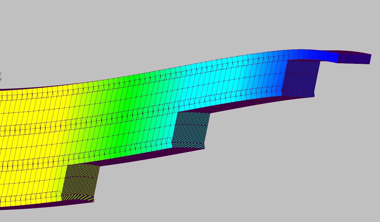
The ortothropic is in the blank space, not shown in the picture. In the image you can see the corresponding nodes on each leaf have shift as there is no Shear modulus (=1 Pa) while manteining the separation.
i’m not really familiar about leaf spring behavior. looking above picture from Disla, it may similar to bonded and slippage of reinforcing bars (ribs or plain) imbedded in concrete block. cohesive element look capable in these specific task, even CalculiX does not have still possible since someone out there was developed for Abaqus (i did not a try yet the compatibility).
Cohesive elements have been available in Abaqus for a long time but here someone developed a special version of them that accounts for fatigue and hydrogen concentration dependency. Abaqus also offers cohesive contact that could be useful in cases like this one, assuming that the leaves are connected with some kind of adhesive. Otherwise, I would stay with no separation contact. However, I still haven’t been able to obtain a good agreement with an analytical solution. Maybe the model is still too stiff or the analytical calculations is too approximate. Anyway, I am surprised that it’s so hard to achieve good match in this case.
¿Would you share your study case to see what I get and compare results?. I mean dimesions of the leaf spring. Geometry as simple as possible please.
I’m corious to see how good is the ortothropic aproach. I will later share my Liml file.
Sure, here are the best deflection results I got so far:
16.66 mm for a full model with no separation contact in Abaqus
12.4 mm for a quarter model with regular contact in CalculiX
17.18 mm for a quarter model without a mounting hole (to which the load is applied in other models) and with no separation contact in Abaqus
The analytical solution is either 15.3 mm or around 22.8 ÷ 22.9 mm. I’m still not sure which formulas are reliable in this case.
The remaining models either didn’t converge (pretty much all of those using regular contact apart from one) or gave significantly overstiffened results (1 mm or even well below, depending on boundary conditions).
My current approach can be summed up like that:
both eyes have free rotation about their axes
one eye has free translation in the direction of spring’s length
boundary conditions are applied to eyes via rigid body constraints
a force of 2000 N (or part of it when the model utilizes symmetry) is applied to the mounting hole via rigid body constraint, in one of the quarter models (without the mounting hole) it’s applied as traction directly to the face of the cut
quarter models have symmetry boundary conditions applied to proper faces, in addition, I had to remove a few nodes belonging to these faces and included in rigid body constraint definition (to avoid overconstraint errors)
the material is standard steel (E=210 GPa, v=0.3)
I attached the step files with the geometry of all the three models discussed above:
And, just in case, main dimensions:
length of the spring (distance between the centers of both eyes): 1171.2 mm
width of the spring: 50 mm
thickness of each leaf (there are 5 of them): 10 mm
the spring is initially curved (load is applied in such a way that it straightens the spring), the main leaf’s radius of curvature is 1250 mm
Here are the best deflection results I got so far:
• TENSION: 25.35 mm and 245.3 Mpa for a half model with Calculix 2.18 / Pastix / MECWAY
• COMPRESSION: Exacatly the same.
Orthotropic seems to respond very nice and not stiff at all. In fact, once the leafs slip is solved the result is very sensitive to the different options of the EYE B.C.
I have disconnected the EYE loop (geometry) as it is in most catalogues Leaf Springs.
The model converges consistently in linear. Tested in nonlinear is not very useful as the elastic contact of the EYE/Stud becomes rigid (??¿¿) and the contact area behaves like tied.
My current approach can be summed up like that:
• Eyes/Stud bonded contact elastic with a minimum stiffness to avoid penetration. It allows rotations of the EYE and horizontal translation of the whole set. See video.
• Boundary conditions between leafs are applied via thin layers of intermediate othotropic material with common nodes. All the mesh needs to be conformal.
• a force of 2000 N it’s applied as traction directly to the face of the cut. Symmetry condition applied to that surface too.
• the material is standard steel (E=210 GPa, v=0.3)
I attached the files.
Thank you so much Could you share a screenshot with symbols of boundary conditions and loads (if Mecway displays them) ? This way I would see how exactly they were applied. Have you defined them on the surfaces between leaves ? The preprocessor that I use doesn’t support all these options and so far I haven’t managed to import boundary conditions and some other features from the input file correctly. Maybe GraphiX would help.
So it seems that the analytical solution is around 22.8 ÷ 22.9 mm, not 15.3 mm like some of my formulas predicted. That’s also important for further studies.
I will try to do some additional tests without the orthotopic layers. Theoretically, no separation contact in Abaqus should work in a similar (or even the same) manner. Maybe even regular contact in CalculiX will eventually work. The key may be to replace the boundary condition applied to the eye via rigid body constraint with more realistic contact with the pin. However, the current approach where the eye has free rotation about its axis and translation in the direction of the spring’s length should provide similar freedom of motion.
All in all, I did not expect it to be so hard to get the results that are not significantly overstiffened in this case. To think that in pretty much all the research papers leaf springs are modeled simply with bonded contact between the leaves and fixed constraints in the eyes. The results presented in them must be completely unrealistic…
Hi,
The most tricky is in the EYE.
There are not special BC’s or contacts inbetween Leafs. That’s why it computes in less than 8 sec.
Nodes are merged so all the layers, materials , are directly connected. The Orthotropic is a thin layer of 0.5 mm. I think I could go even smaller.
I manually meshed the model so all is structured and conformal.
If you can’t get it you will have to impose some contact BC between the layers. I have not try it.
Where it says displacement < > it is displacement =0.
Let me know if you need any other view.
I prepared a new test model. It utilizes double symmetry (a quarter of the spring) and includes a pin in the mounting hole like in your case. Here are the boundary conditions shown from two sides:
As you can see, symmetry boundary conditions are defined for proper faces. In addition, the outer face of the pin is also fixed in the U1 direction and for the whole pin U3=0. The face where U2=0 BC is applied has a surface traction load with a magnitude of 500 N.
When it comes to the remaining settings, hard frictionless contact is applied between the leaves while tied contact is used for the pin-eye interface. All contact interactions have adjustment enabled. Orthotropic layers are not used at this point - I assume that this replacement for no separation contact may not be necessary in cases where regular contact converges since the latter allows for even more flexibility of the connection.
The model converges well but the results are far from the expected values. The maximum deflection is 7.672 mm.
I’ve noticed that you applied a force of 2000 N in your model. Shouldn’t it be 1000 N since symmetry in one plane is utilized ?
With the EYE tied to the Pin but the PIN free to rotate, 24.31 mm. Or maybe some middle point, let’s say, Eye free to rotate around a non-rotating PIN but with some friction between them. I think thts situation would be nice. One or the other I would not forget the slide between leafs.
This second case (with the result of 24.31 mm) is pretty close to the analytical solution. How did you allow the pin to rotate ? Can you share the input file or (maybe even better) screenshots showing modified boundary conditions ?
I was thinking about making the pin rigid but this could have a negative impact on the results.
I also tried replacing the tied contact with tie constraint but it failed to converge for some reason. Maybe because of too small tolerance.
Your intuition is correct. You need to transform the PIN into a rigid body with the REF NODE on the Axis of rotation of the pin.
Example: *RIGID BODY, ELSET=EYE_FULL ,REF NODE=7806
Apply the U1 and U3 BC TO the REF NODE and let all the other nodes on the pin free to do whatever they want.They will follow the REF NODE as it is a RIGID BODY but the set is free to rotate.
Why “this could have a negative impact on the results”?


 Could you share a screenshot with symbols of boundary conditions and loads (if Mecway displays them) ? This way I would see how exactly they were applied. Have you defined them on the surfaces between leaves ? The preprocessor that I use doesn’t support all these options and so far I haven’t managed to import boundary conditions and some other features from the input file correctly. Maybe GraphiX would help.


