C3D20 and S8: Different results

Hello, dear colleagues,

I am currently investigating non-circular, thin-walled cylindrical shells under external pressure. Typical parameters are: mean of the two main axis dimensions 1000 mm, wall thickness 22 mm, out-of-roundness 0.015. Out-of-roundness is defined as the quotient of the difference between the two main axis dimensions and their mean.

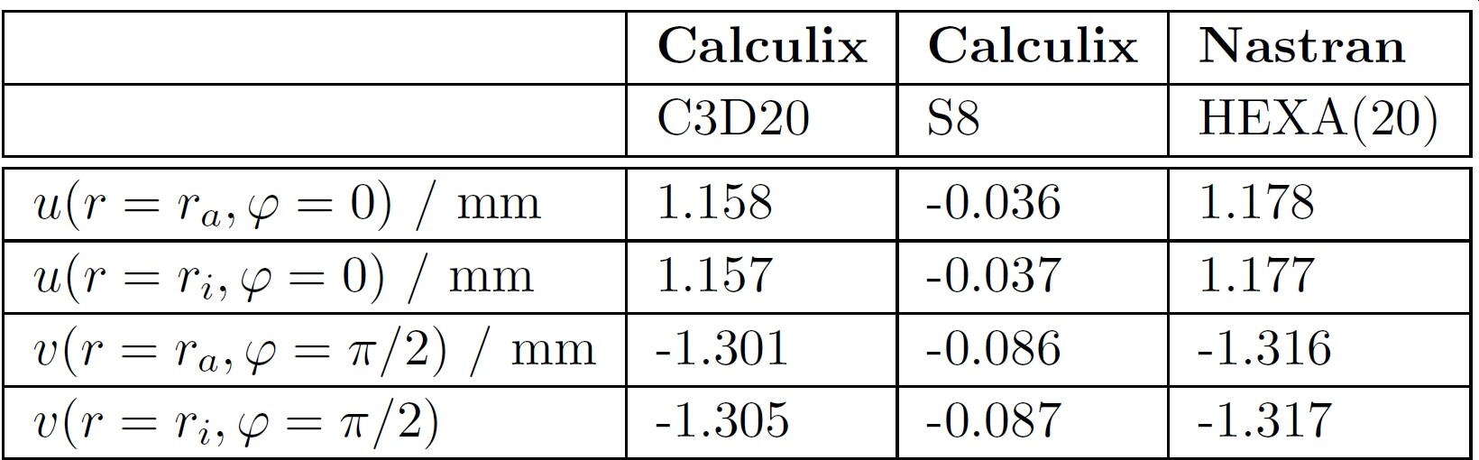
I am calculating with linear-elastic material (E = 188000 MPa, nu = 0.295) and geometrically non-linear. I am using two different models: Model A with 20-node hexahedral elements, Model B with 8-node shell elements.

I have learned that Calculix converts 8-node shell elements internally into 20-node hexahedral elements before the analysis. Since I am using a single element across the wall thickness for model A, I actually expect the results to be identical for both models.

Unfortunately, I don’t see that. I get the following displacements for a pressure of 1 MPa and boundary conditions for infinitely long pipes:

I also see large deviations in the stresses:

The buckling pressures also differ:

I did the analyses under Windows 11. The two inp files can be found here: ell_inf.zip - Google Drive

I believe that the results of model A are correct because I confirmed them with NX Nastran. They also agree quite well with the publication /1/ from 1950.

It is also interesting that I get no differences in the displacements and stresses for perfectly round cylinders. Only the buckling pressures are unchanged compared to the non-round models. The models for the perfectly round cylinders can be found here: cyl_inf.zip - Google Drive

I would like your support and advice. I don’t want to rule out that the error is mine. On the contrary, it could be likely;-)

Greetings, thanks in advance
muppets

/1/ S. Schwaigerer, A. Konejung, Die Festigkeitsberechnung von Flammrohren. In: Konstruktion, 2 (1950), No. 1, pp. 17-23

That’s no accurate since shells are joined at the nodes by knots so they can provide rotational degrees of freedom.

Try removing the simmetry bc on the shell model, use a complete model instead. There is a bug on the symmetry on curved shell elements if I rememeber well.

1 Like

there are several warnings when running the shell model:

*WARNING in usermpc: no MPC is
generated for the mean
rotation in node 4
and direction 6

*WARNING in usermpc: no MPC is
generated for the mean
rotation in node 91
and direction 6

*WARNING in usermpc: no MPC is
generated for the mean
rotation in node 92
and direction 6

*WARNING in usermpc: no MPC is
generated for the mean
rotation in node 93
and direction 6

*WARNING in usermpc: no MPC is
generated for the mean
rotation in node 94
and direction 6

*WARNING in usermpc: no MPC is
generated for the mean
rotation in node 95
and direction 6

*WARNING in usermpc: no MPC is
generated for the mean
rotation in node 96
and direction 6

*WARNING in usermpc: no MPC is
generated for the mean
rotation in node 97
and direction 6

*WARNING in usermpc: no MPC is
generated for the mean
rotation in node 98
and direction 6

*WARNING in usermpc: no MPC is
generated for the mean
rotation in node 99
and direction 6

*WARNING in usermpc: no MPC is
generated for the mean
rotation in node 3
and direction 6

*WARNING in usermpc: no MPC is
generated for the mean
rotation in node 82
and direction 6

*WARNING in usermpc: no MPC is
generated for the mean
rotation in node 83
and direction 6

*WARNING in usermpc: no MPC is
generated for the mean
rotation in node 84
and direction 6

*WARNING in usermpc: no MPC is
generated for the mean
rotation in node 85
and direction 6

*WARNING in usermpc: no MPC is
generated for the mean
rotation in node 86
and direction 6

*WARNING in usermpc: no MPC is
generated for the mean
rotation in node 87
and direction 6

*WARNING in usermpc: no MPC is
generated for the mean
rotation in node 88
and direction 6

*WARNING in usermpc: no MPC is
generated for the mean
rotation in node 89
and direction 6

*WARNING in usermpc: no MPC is
generated for the mean
rotation in node 90
and direction 6

pressure is applied in different sides of the structure:


1 Like

Thank you. I understand that. But I wonder if that explains the big difference between the two results.

Thank you! I tried that and indeed the differences become much smaller.

1 Like

Thank you again for your help! The warnings regarding MPCs apply to the nodes with the symmetry boundary conditions sym_x and sym_y. I don’t quite understand what triggers these warnings. I split now the two boundary conditions so that the rotations around the z-axis are blocked separately. This made the warnings disappear, but the results remained the same.

I used Prepomax to create the model. I think I chose the outside there.

Thank you again!!!

Great! For the solid body, I would try with 2-3 elements in thickness also. And remember that for comparing results between solvers (or maybe even for the same solver but different kind of element), the results must be converged, because Calculix could need more nodes to get an “accurate” result than Nastran, or the solid one compared with shells.

1 Like

Rotational DOF constraints should only be about axes in the plane of the shell. Sometimes it sort of works when they’re in other directions but it also randomly over-constrains it sometimes.

Many of the constraints here are in arbitrary directions which is pretty risky. You can remove the drilling DOF constraints on the ends because they do nothing anyway. Along the curved edge, you should use *TRANSFORM with a single constraint on each node so that no component of it is normal to the shells.

Sorry my results are not accurate. I was reviewing discrepancy and noticed this note on your input data:

That’s the plane strain condition. My BC ( I think yours too) don’t fullfill that condition so I would like to look at that.

Updated: Linear Buckling on the left with buckling pressure 5.58MPa and Nonlinear on the right with buckling pressure 4.0 +/- 0.1 Mpa

@SergioP: For fun, I worked with 10 elements across the wall thickness in the solid model, the differences are small. Otherwise, you are of course absolutely right. You shouldn’t overdo the comparison of results with different solvers and/or elements. It is the nature of things that there must be certain differences. However, I was unable to explain the original, large differences with the C3D20 and S8 elements, which is why I asked my question here in the forum.

@vicmw: That explains the differences in the results. I will work with *TRANSFORM as you suggested and report back.

@Disla: Thank you for the tip about the boundary conditions. I was a bit naive and assumed that for an infinitely long pipe, every plane perpendicular to the z-axis must automatically be a plane of symmetry. But of course using the plane strain state is more accurate. The buckling pressures are very interesting in my opinion. If you consider the perfectly round, infinitely long pipe with the same average diameter and the same wall thickness, you get a buckling pressure of 5.58335 MPa (The value is identical to the buckling pressure of the non-round pipe, which you can read for example in the publication /1/. However, this shall not play a role here). For an infinitely long pipe, you can read the buckling pressure in /2/: p_crit = 0.25 * E / (1 - nu^2) * (h / R)^3 = 0.25 * 188000 MPa / (1- 0.295^2) * (22 mm / 500 mm) ^3 = 4.38528 MPa. This value is exactly between the two values ​​you determined (for the non-round pipe). May I ask you to explain how you calculated the non-linear buckling?

@All: Thank you so much for your help!

/1/ S. Schwaigerer, A. Konejung, Die Festigkeitsberechnung von Flammrohren. In: Konstruktion, 2 (1950), No. 1, pp. 17-23

/2/ S. P. Timoshenko, J.M. Gere, Theory of Elastic Stability, Second Edition

1 Like

Just for clarity : I’m not suggesting to use CPE8 elements.

For the Perfect Circle, the snap is neat and I’m getting 4.371 MPa

Increase the pressure quasi-statically until the cylinder collapse. Depending on the geometry the snap will be more or less abrupt. Convergence failure can be an indicator (Perfect Circle). If not, the buckling initiation is not so easy to identify as in the imperfect pipe model.
In this case I’m looking at the reaction force at the wall ( what you call INTERNAL_SELECTION-1_SYM_X)

You have some Nonlinear buckling posts in the forum.