Hi everyone,
I am trying to do the 2-step simulation for pre-stretch structure.
Step1: I apply the displacement as the boundary for static analysis to get the pre-stretch. It is succeed. Then I change the Step1.rout into Step2.rin file.
Step2: I give a load along the y direction on surfaces. After finishing the simulation, I check results and find that results are the same with the Step1.
My setup files are shown in this link GitHub - NUGUY2022/2step_simulation.
I want to get some helps. Thank you!
hello,
how can we help?
have you already looked / searched here in the grouped for previous conversation,
like these:
*pre-tension with solid elements - CalculiX
i had maybe some simular points, please check my topics
Hi dichtstoff,
I have read all these conversations and setup files according to them. But I check my setup files many times and can’t find the reason why the structure is not deformed when I give a constant load along the y direction on surfaces. Is the force too small? Could you help me check the file? Thank you so much.
Have you solve Step 2 without pre-stretch?
How do someone download the whole set of files from a github repository?
Yes, Step2 without pre-stretch.
You can download by clicking the green Code and then clicking download zip.
I can read in the frd file
1UPGM CalculiX
1UVERSION Version 2.11
¿Which ccx version are you using. We are at v2.21?
I use Calculix 2.20. I check the frd file in PrePoMax and find that results are the same with the Step1. It makes me confused.
It seems that the problem is with this part of the input file:
*BOUNDARY,FIXED
**INCLUDE,INPUT=Solid/boundary-restart.inp
**BOUNDARY,OP=NEW
*Nfix1,1,1,0
*Nfix1,2,2,0
*Nfix1,3,3,0
I would change it to e.g.:
*BOUNDARY,OP=NEW
Nfix1,1,1,0
Nfix1,2,2,0
Nfix1,3,3,0
Then you should get different results from each step.
I think I have arrived at the same conclusion.
Step1 is writing / transferring geometric BC to Step2.
*STEP, NLGEOM, INC=1000000
*STATIC
1.E-3, 1
*RESTART,WRITE
*INCLUDE,INPUT=boundary.inp
You can clean with OP=NEW in Step2 or maybe try to exclude the *INCLUDE card from the write changing the order.
*STEP, NLGEOM, INC=1000000
*STATIC
1.E-3, 1
*INCLUDE,INPUT=boundary.inp
*RESTART,WRITE
By other hand, I would say this kind of analysis is intended for FSI interaction where you need a stop to compute external loads in other software for later update in an iterative process. If your *CLOAD is as simple as it is there is no need to write , read.
My final aim is for FSI interaction using Openfoam, Calculix. So I need to do like this. I modify the setup files according to yours. The result is not what I want.
1.I change this section into
*BOUNDARY,OP=NEW
Nfix1,1,1,0
Nfix1,2,2,0
Nfix1,3,3,0
The low boundary is not fixed and the structure is moving along the y direction.
2.I change the order of *INCLUDE,INPUT=boundary.inp.
It doesn’t work. The result is the same with step1.
I have found an additional issue probably due to some language misunderstanding from my side:
*BOUNDARY,FIXED is used in the second step.
Manual says: the FIXED parameter freezes the deformation from the previous step, or, if there is no previous step, sets it to zero.
What does this mean?.
- Is there a previous step if *RESTART,READ is used.?
-What does Freeze means?. There will be no possible additional deformations no matter what BC is applied?
- If there is no previous step, deformation is just set to zero or is set to zero and freezed?
Mine is not moving.
*INCLUDE, INPUT=all.msh
*INCLUDE, INPUT=fix1_beam.nam
*INCLUDE, INPUT=interface_beam.nam

*MATERIAL, Name=EL
*ELASTIC
12000000, 0.3
*density
1000
*SOLID SECTION, Elset=Eall, Material=EL

** fix on the lower boundary from x to z.
*BOUNDARY
Nfix1, 1, 3

*BOUNDARY
Nall, 3

*STEP, NLGEOM, INC=1000000
*STATIC
1.E-3, 1

*INCLUDE,INPUT=boundary.inp

*RESTART,WRITE

*NODE PRINT, NSET=Nall, FREQUENCY=1000
U
*NODE FILE
U
*EL FILE
S,E,ENER
*END STEP
*RESTART,READ

*BOUNDARY
Nfix1, 1, 3

*BOUNDARY
Nall, 3

*AMPLITUDE,NAME=AMP2
0,0
1,1

*STEP,NLGEOM,INC=1000000
*DYNAMIC
0.01, 1
**BOUNDARY,FIXED

*BOUNDARY,OP=NEW

Nfix1,1,1,0
Nfix1,2,2,0
Nfix1,3,3,0

*CLOAD,AMPLITUDE=AMP2,OP=NEW

Nsurface, 1, 0
Nsurface, 2, 10
Nsurface, 3, 0
**NODE PRINT,NSET=probe
**U
**NODE PRINT,NSET=Nfix1
**U
**NODE PRINT,NSET=Nsurface
**U
*NODE FILE
U
*EL FILE
S
*END STEP
I have tried your setup. The structure is not moving but the same with the step1.
What if you merge the input files instead of using restart ?
mmhhh ![]()
1-Are you sure you are opening Step2.frd?
2-Your Step2.frd is a dynamic analysis and contains Step1.frd. You need to go further than time 1s to see the Step2 in action.
NOTE:Sorry about my English.
I checked results again. I am sure I check the second 6 because I set the dynamic analysis time 6s. The checking conclusion is the same as above. Don’t mind English. I can understand what you say. Now I am trying to merge the input files.
I have found the main problem. This section is wrong:
*BOUNDARY,OP=NEW
*Nfix1,1,1,0
*Nfix1,2,2,0
*Nfix1,3,3,0
We need to remove the " * " before Nfix1
*BOUNDARY,OP=NEW
Nfix1,1,1,0
Nfix1,2,2,0
Nfix1,3,3,0
I updated the setup files.
Thank you so much !
Check your results carefully.
I can see a small difference between the final displacement in Step1 and initial displacement in Step 2.
Steep2 pre-stretch value is slightly smaller than what it should (obtained in Step1)


Thanks for your patience. My new setup file shows a significant difference between Step1 and Step 2.

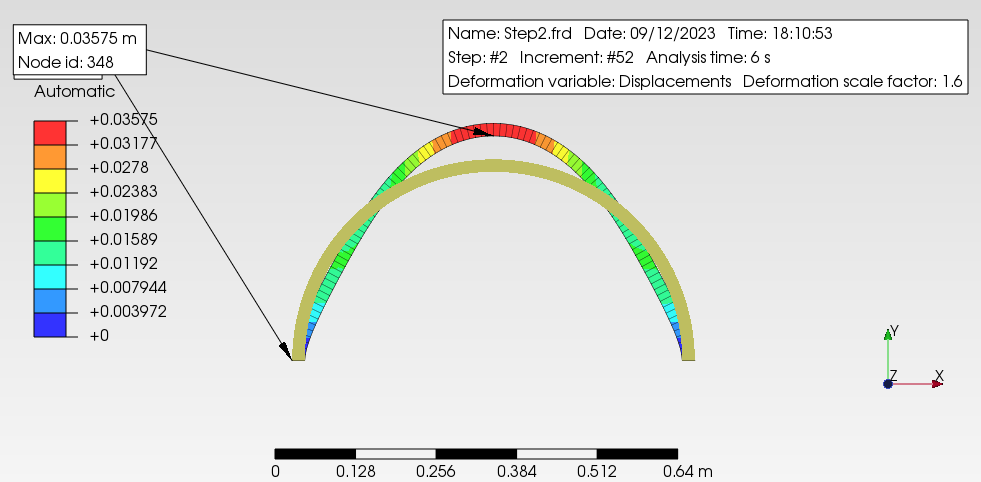
Please check it.
I mean the maximum prestretch value.
Should be the same and it is not.
Maximum displacement of Step1 = 1.31mm
Initial prestretch Step2 = 1.14 mm