Hello everyone,
I am trying to simulate the interaction of a beam under bending while the whole body (every node) is subjected to a (unidirectional/orthotropic) thermal expansion:
A cantilever with a fixed support on the left side is subjected to a force perpendicular to the beam axis at the free end on the right side. The maximum displacement occurs at the free end.
Additionally, a thermal expansion is applied, which makes the beam longer (only in longitudinal direction so the cross-section remains constant) and therefore the deflection should be higher compared to a purely mechanical simulation.
The purely mechanical simulation without thermal expansion works fine and the maximum displacement corresponds to the analytical solution
wmax = 1/3*F*L³/(EI) = 1/3*(1050000N)*(2.00m)³/(210000e6N/m²*1/7500 m⁴)
     = 0.1 m
with a rectangular cross-section b/h = 0.2/0.2 m
If I apply a thermal expansion and the length of the beam becomes Lth = 2.8m, the maximum deflection should be
wmax = 0.1m*(2.8m)³/(2.0m)³
     = 0.2744 m
but I still receive the same deflection of 0.1m.
I tried different simulation types (*Static, *Uncoupled Temperature-Displacement, *Coupled Temperature-Displacement) and different ways to increase the temperature (*Initial Conditions=Temperature with *Temperature or *Boundary DOF 11). Sometimes I received error messages, that either the initial temperature or the final temperature in a node is not specified.
Here is one input file of a working simulation, even though it took 3 hours to finish.
************************** Mesh ***************************
**
*INCLUDE, INPUT= ./all.msh
**
**
****************** Node and Element Sets ******************
**
**In ./all.msh
**
**
************************* Materials ************************
**
*Material, Name=DummyMat
*Elastic
210000e6, 0.1
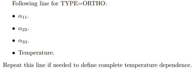
*Expansion, Zero=273.0,TYPE=ORTHO
0.005,0.0,0.0
*DENSITY
7850.0
*SPECIFIC HEAT
500.0
**
**
************************* Sections *************************
**
*Solid section, Elset=Eall, Material=DummyMat
**
**
*************************** Step ***************************
**
**Time Points
*TIME POINTS,NAME=T1,GENERATE
0.0,10.0,1.0
**
**
**
** Supports
*Boundary,fixed
Nsurfleft,1,3
**
** Initial Temperature
*INITIAL CONDITIONS,TYPE=TEMPERATURE
Nall,273.
**
**
*Step,NLGEOM=YES,INC=10000000000
*COUPLED TEMPERATURE-DISPLACEMENT
1.0e-2,10.0
**
**
*Cload
Nsurfright,3,-16150
**
**
**Temperature
**Nall,353.0
**
*BOUNDARY
Nall,11,11,353.
**
** Output .frd
*Node file,TIMEPOINTS=T1
RF, U, NT
*El file,TIMEPOINTS=T1
S, E, NOE, ENER
**
** Outputs .dat
*NODE PRINT, NSET=Nsurfright, TOTALS=ONLY,TIMEPOINTS=T1
RF
*NODE PRINT,NSET=Nall,TIMEPOINTS=T1
U
**
*End step
**
I used C3D20R elements. The cload is applied to 65 nodes at the free end.
Any idea how I can adjust the simulation for increased deflection due to thermal expansion?
Thanks,
Felix


