what about this:
*STEP,NLGEOM=YES,INC=100,AMPLITUDE=STEP
*STATIC,DIRECT
0.01,1,0,0
what about this:
*STEP,NLGEOM=YES,INC=100,AMPLITUDE=STEP
*STATIC,DIRECT
0.01,1,0,0
I would try:
By default I use fixed time increment in my models, I feel more comfortable having a straigh division of the applied load.
I understand, but is a difference with Calc_em’s model. Sometimes makes models more difficult to converge than with automatic incrementation, maybe here is the opposite.
you changed a lot of things…
In fact, I just import the geometry step file and create a new model without seing how it was made in Prepomax. I made with my standard tools and procedures that works razonably well ![]() at least in my models.
at least in my models.
seems a solid approach, I learned a lot, however it does not provide a hint about why Calc_em’s approach does not work.
There are some extra bc like rigid bodies that add extra complexity to the model, and the use of a full model where it can be solved for a smaller one leads to a model hard to debug. Start with a simple model and then add more details.
I need friction in this model but I can change its value. It hasn’t helped previously though.
I tend to avoid fixed incrementation because its use is heavily discouraged in Abaqus. But Abaqus has better auto incrementation algorithms.
I’ve tried that but it didn’t help. Maybe even made it worse, probably due to master-slave mismatch.

I already use linear elements but I haven’t tried 1 layer yet.
I don’t need accurate stresses, it will be more about forces.
The model is already quite simple. One rigid body makes it even simpler in a way (by reducing the number of DOFs) and the other one is far from the problematic area and included mostly for convenience. The issue seems to be caused by a combination of unfortunate geometries in contact and contact conditions/algorithms themselves. I’ve tried several different variants of the geometries though and to no avail.
I have a solution to your problem (reduce your maximum time step to 0.01s)
But not sure about the source of the issue.
It must probably be related with JuanP74 crucial question : How can it be ccx declares this increment as converged?
I could explain some penetration but not sustained contact gap (specially during flat top run).
Contact stiffness changes during the step, probably to help convergence.
Adjustment only takes place if the “waters are calm”
Give it a try. Provide a large initial time step to get a nice separation.
Stop the block at the middle of the run for a few time steps before continuing and the gap closes.
Kind of Contact stiffness relaxation. Known that, there could be different solutions to get good results.
Thanks. Sounds reasonable (otherwise, CalculiX may jump through equilibrium configurations) but did you change anything else (like contact settings, for instance) ? Did you recreate the model in Mecway ? Because when I only change the initial and maximum increment to 0.01 in my original file, it runs until 0.466250 and then fails with:
 *ERROR: too many cutbacks
 best solution and residuals are in the frd file
As suggested by Sergio I recreated the model in Mecway reducing a lot the number of elements. Just for debugging purposes. One element in depth from your mesh and removing the large base.
The complete model was too much time, but I think I can help anyway.
Look at Juan formula 0.5*(E_stiff+E_less_stiff)/L_char
Around 0.46s the contact area has L_char=0 as it is only sustained by the edge. I would increase your K *10.
I’ve tried that (K=100000000 N/mm^3) but it failed even earlier - at 0.1925. I guess that a combination of changes is needed to get my actual model running. I simplified it to have just a single layer of elements in the thickness direction by replacing the transfinite mesh with extruded one (had to replace the geometry with the one having surface partitions instead of volume partitions):
Should be easier to do the tests in PrePoMax or directly with the input file.
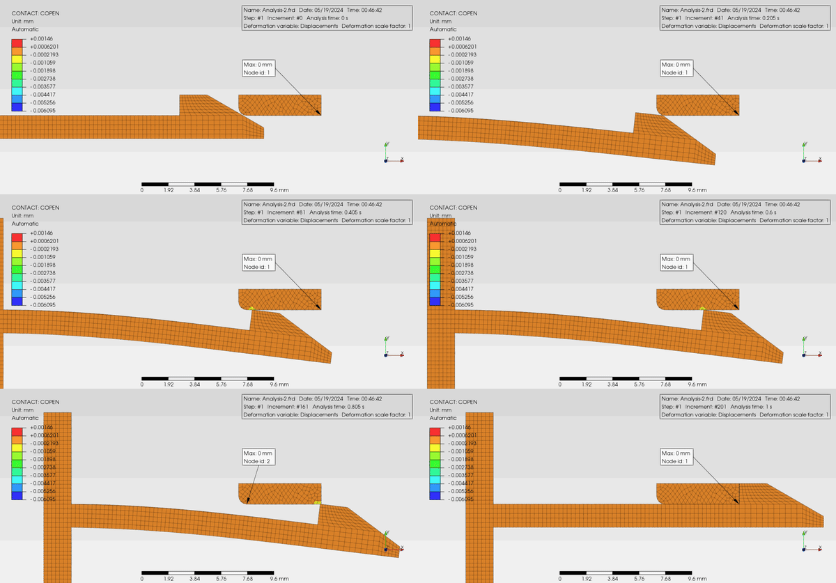
since many reported a problem, i recreate another similar cases.

p.s plot deformations are in true scale.

This would be my approach keeping the original geometry.
I still don’t have answer to JuanP74 question.
Max time step to 0.005 s
Reduced K=80000 N/mm3
Reduce Stick Slope.
*Surface interaction, Name=Surface_Interaction-1
*Surface behavior, Pressure-overclosure=Linear
80000, 2.86
*Friction
0.3, 1
C3D8R
Add back surface of the brick to the contact pair definition.
Swap Master Slave.
Tabulated Amplitude to invest more time steps into difficult transition areas.
Remove Rigid Bodies. (Too Stiff and I don’t like Rigid bodies on top of contacts).
Increased maximum overall number of iterations and particular to 150 by means of CONTROL (Some itrs reached U value).

the problems are in unexpected additional bending due to kickback action and post deformed configuration at end steps increment. Both of the problems may be caused by friction definition and displacement control, smooth transition seems not really a problem since it did not change overall behavior.
it could be interesting when sketch of problems are provided, all output generate by Abaqus including displacement, stress and contact pressure. Original example geometry is quite simple to recreate, another user may need to check by reduced mesh or element type, contact type, etc. I have seen the part has been partitioned and needed further editing to clean up.
below my previous simplified models with hard contact, friction and rigid bodies.

Very nice job! congrats. Swapping master-slave and removing rigid bodies also improved situation a lot for me but still had some issues despite refining the mesh.
One thing I was wondering is if it would work better if there was contact in the initial configuration.