I’m analyzing an RC (reinforced concrete) beam with a rectangular cross-section and two steel bars in its lower part (no interactions/constraints - all parts are merged into a compound). The beam is subjected to pure bending. I used compression-only material for concrete. The maximum stresses in concrete are close to the expected value but the stresses in rebar are way too low:
Any ideas what I am missing ? Mesh refinement doesn’t seem to help much. At some point it even led to non-convergence.
I wanted to try it in Abaqus as well but it doesn’t converge there with the compression-only material (Abaqus doesn’t have that option to allow for some small tension to aid convergence) even when embedded beam elements are used instead of solids for rebar.
In frd file you have stresses averaged. If you want to avoid it, tied constraints between separated solids can be used so ccx doesn’t average the stresses in the output.
I’ve tried with tie constraint but the stress is still too low. Maybe I should try refining the mesh (and using hex elements) but again - it may lead to non-convergence.
Yes, I have 1 MPa of maximum allowed tension but this is just to make it converge (in Abaqus, it doesn’t converge at all because even a very small tension is not allowed).
I don’t take temperatures into account here. The analysis is only meant to provide results agreeing with those shown in the YouTube video (it’s a simple exercise from Mechanics of materials book).
stress about half only from expected, can sketch problem and boundary condition (support and load symbol) provided? another possible is related to size effect and uniaxial response as in video links.
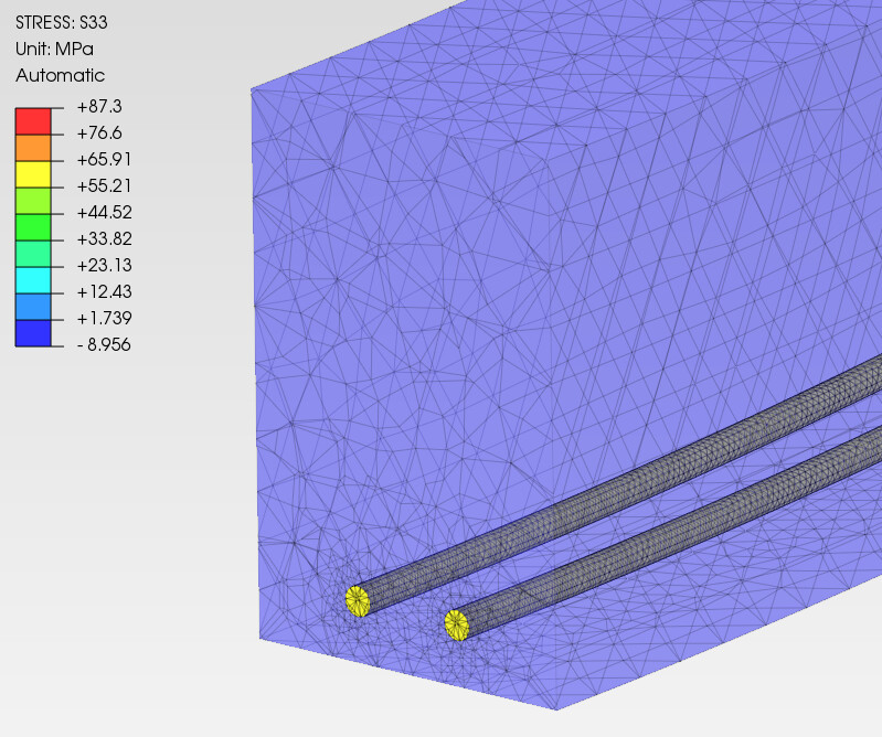
So there are rigid body constraints attached to both end faces (yellow). Their reference points have only UR1 unconstrained (the other DOFs are fixed) and opposing moments are applied in that DOF on both ends (-60000000 Nmm and +60000000 Nmm).
All this is defined to simulate pure bending (the exercise assumes only the bending moment acting on a section of the beam) while avoiding convergence issues.
beam length and load assignment seems it was normal and properly set.
if the condition is true then i will trust FE result first since in balanced condition and equilibrium, is satisfied, about half result of stress in rebars may indicated some erroneous is analytical calculation.
i’m only quick in view of video links, this approach is an old and known as working stress in early reinforced concrete design. It seems inconsistent notation, in previous minute use total rebar areas but later is each rebars, maybe it counts double.
I guess you need a simply suported beam for the moment to properly develop across the beam.
That is unconstraining Uz at one side.
Anyway I would measure the bending moment at the midsection to be sure you are reaching the required 60KNm
The program doesn’t know the 1mpa is just for convergence. It may be 1 mpa, but it is as much as 50 times the area of the rebar. The input for the steel and concrete materials has temperatures. Make sure they are the same for all materials. Change the max tension some and notice how large a change you get in the bar strasses. Yes it is difficult to converge with compression only materials. Note also many problems end up with internal arching not accounted for with classical methods.
I’ll have a closer look at the exercise solution in the book (the video is only following it).
I tried *SECTION PRINT in the middle of the beam and got 5.978354E+07 Nmm for the current support scheme and 5.978097E+07 Nmm for the modified support scheme (U3 released at one end).
I don’t have analytical results for deflection, only for stresses. I use a ready solution from Hibbeler’s book. Maybe there’s a mistake in it but I’m not really familiar with civil engineering calculations: