Has anyone implemented a mesh partitioning to implement a combination of hex and tet element types (not hex dependent meshing but actual partitioning of mesh)? Is it essential to assign contact/tie at the interface of the two meshes if all nodes are shared at the interface? In Abaqus, two element based-surfaces are created by default , and tied to each other as master-slave when implementing different element types after mesh partitioning.
If you have two separate meshes, one hex and one tet with the same position of nodes at the common surface, you have two options. You can tie the surfaces together or you can merge the coincident nodes. That would give the same result if you are using linear finite elements. If you are using quadratic finite elements, merging the nodes would not work in the same way since tet mid-nodes would not get connected to anything.
If you have two surfaces with non-coincident nodes the only option is the tie/contact option.
But in each case you have to add it manually. It will not be added automatically.
Many thanks for the response. So far, all nodes in the interface region are shared. However, Since I do not create my mesh in cgx, I probably do not have the option to use cgx neigh command. Does cgx have the option to edit mesh from inp file ?
My issue with the *TIE command is that the master surface must be defined using faces and not nodes. Since I create my mesh elsewhere, I do not have info on the element faces, but the nodes. Any suggestion is highly appreciated.
To give you a context, this is what the FE mesh look like. The interfaces are visible towards the tip and tail section.
hello manny,
you may use cgx to read your abaqus (ccx) mesh with
cgx -c file.inp
Then either use existing sets or create one with
seta ! all
and display the element faces
plot f +CF1
Then select faces with
qadd set1 t1
see details in the manual.
Finally send the set with
send set1 abq sur
I tried PrePoMax, On a simple cantilever domain with half hex and half tet elements, they get merged into a single part (I was expecting them to be multiple parts), yet the interface remains, as is shown by high stress concentration at the interface. Enforcing tie constraint fail as well : *ERROR in cascade: zero coefficient on the dependent side of an equation dependent node: 2049 )
Not sure if the error arises due to the fact that the nodes of the two sides being tied are essentially the same. Will play around on simpler cases and see if that works. Let me know what you think.
Thanks Klaus, I was able to read my mesh in cgx. However, the interface faces are not being shown when doing plot f +CF1 for some reason. I am using bconverged with cgx 2.10. Let me know if you happen to have similar example that I could test on.
PrePoMax splits the mesh into non-connected parts. If two parts share one node, they are merged. If you create an element set you can then convert the element set into a part (right-click → Convert to part) and have connected parts. Then you can create surfaces on the outer sides of a part.
In the case, where the nodes are merged the tie constraint is not necessary - it will not work. The meshes must be separate. I was under the impression that Abaqus also uses a separate mesh and adds the tie constraint. Is this no the case?
I see that you are using a concentrated force load? This load assumes a load on all selected nodes. For surface load use Surface traction load.
Hello manny,
please type
prnt se
Then you should see the available sets. I guess that the version of cgx which you use is too outdated.
The bconverged binary of cgx is even older than 2.10. You may replace it with the binary provided in the same text line at www.dhondt.de were you find the bconverged distribution. Just follow the README in the update package.
Hi Matej,
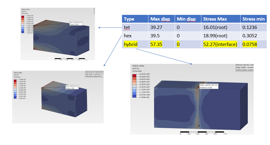
Many thanks for your help. Does PrePoMax automatically merge the mesh if nodes are coincident? I assumed so but the results are not accurate. Below is tet,hex and hybrid case comparison in Prepomax. I’m also attaching a google drive link to the calculix and the pmx file in case you would be interested in having a go at it.
Hello Klaus,
Thanks for the suggestion. I was able to update my bconverged to 2.17 build of ccx and cgx. I’m still unable to view and select the interface faces, not sure if I’m doing the cgx commands right. Using neigh command to merge the meshes at the interface hasnt worked either. Nonetheless, I’m sharing my ccx files in case you’d be interested in having a look.
The mesh you have imported already has merged nodes. The nodes of tet and hex meshes were not merged in PrePoMax since such functionality does not exist at the moment
On my side the command
seta ! all
produces the +CF1 set. But only this set which means that the mesh is merged. It will be hard for you to catch the right remaining nodes so you better divide the mesh. In cgx you could use the sets +C3D8 and +C3D4.
send +C3D8 frd c
send +C3D4 frd c
Then
cgx +C3D8.frd
read +C3D4.frd add
And the two element types are disjunct again and you can use
seta ! all
successfully to create +CF1 and +CF2 etc.
hi,
in case you’re using GMSH as preprocessor (modeling & mesher) seems there’s two possibilities to connect the part. defining group of face by physical surface of coincident faces to connect by tie constraint, another approach are using BooleanFragments capabilities. may i can be seeing further if an example of geo file is available.