Hello, everyone!I am calculating a fluid-structure coupling problem that simulates the collapse of a bubble in water at the boundary of an elastic structure.The collapse of the bubble impacts on the elastomer boundary (i.e., the contact surface between the fluid and the solid).But I’m noticing a weird stress distribution on the elastomer surface, I feel like it’s volume locking?
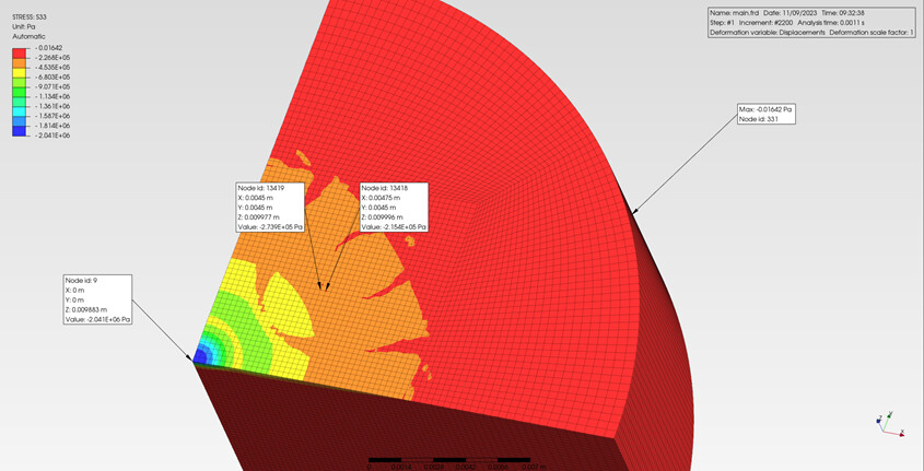
Figure 1 illustrates the S33 distribution of the elastomer at the moment of impact, where the elastomer is linearly elastic with a modulus of elasticity of 5e6Pa, Poisson’s ratio of 0.4, and a density of 1300 kg/m^3.The element type used is C3D8.
Figure1
As far as I know fully integral elements can lead to volume locking, in addition to larger Poisson’s ratios.
So I used the C3D8 element but changed the Poisson’s ratio to 0.3 and did the calculation again, and I still have this problem.Figure 2 illustrates the results of the calculation
Figure2
Then I changed the element type to C3D8R with a Poisson’s ratio of 0.3 to get the results when the elastomer is subjected to an impact, and it looks like there’s a slight improvement as shown in Figure 3.
But it also occurs in later time steps when the elastomer is recovering, as shown in Figure 4.
I’m not so sure this is volume self-locking.Or is it a phenomenon caused by the forces of fluid transduction.If it’s volumetric self-locking, do I optimize the meshing or change the geometry of the computational domain?
If you have a better suggestion, I’d appreciate it!
Then it shouldn’t be volumetric locking since it occurs with incompressible and nearly incompressible materials such as rubbers and metals at large plastic strains. You should also check if there are large stresses without significant displacements.
I know this is against Ockham’s Razor but, have you consider those patterns could be surface wave patterns.You are using hyperelastic material (solid media) ¿isn’t it?
Interference patterns inside a cylindrical container.
If you have an impact you can induce P , S and surface waves.
¿Do those patterns also show up in deep?.¿Do they propagate? ¿What do the animation view say?
It would be good to investigate such patterns with averaging turned off (commonly done in Abaqus) but it’s not really possible in the case of CalculiX.
It might be worth looking at the integration point values of the stresses. They should be smoothly distributed among neighboring elements. If they are not, then that hints at a possibly bad choice of element type.
Thank you all very much for your suggestions!
I’ll check the stresses and displacements at the nodes.May I ask if anyone knows the way to output the displacement and stress of nodes on a surface in calculix or in prepomax post-processing?
In addition to this, I’d like to ask for advice : I’d like to model elastomer deformation as having a large enough effect on the flow field, but the effect is barely visible at the moment. How much can a linear elastic material deform, please? I am not sure if it is possible to have a significant effect on the flow field?
Thank you very much!
Do you need individual values for each node or total values for the whole surface ? For the former you can use history output (*NODE PRINT) while for the latter you can use Query in PrePoMax.
Linear elasticity is rarely sufficient for elastomers. It should be used only up to a few percent (approx. < 2%) of strain. Then you should use hyperelasticity.
Thanks to everyone for all the suggestions!
I looked at the strains at the fluid-structure interface and when the structure receives an impact, the maximum strain is about 0.24 which is 24% of the strain percentage(As shown in Figure1,E=5e5Pa,density=1300kg/m^3,Poisson’s ratio=0.4), so linear elasticity is no longer appropriate is it? I need to use hyperelastic material model?Otherwise the structure would be too stiff?
In fact I would like to simulate the rebound phenomenon of an elastomeric structure, if the structure deforms upwards enough it can have a sufficient effect on the flow field. So can I achieve my goal with a hyperelastic material?
Figure1
This is the maximum strain of an elastomer subjected to impact, which I simulated with abaqus.where E=7.9e5Pa, density=1060kg/m^3,Poisson’s ratio=0.45.
Yes, those are quite significant strains. Too large for linear elasticity, it just won’t give you accurate results. Hyperelasticity should be used in this case.
Then those were waves?. Aha…
Known your material parameters, your maximum wave speed is around 53.17 m/s (You can check measuring the required time to detect the first perturbation arriving at the outside of your model).
Rayleigh waves are much slower than bulk (maybe around 5 m/s -15 m/s).
I would first run a 2D shell dynamic explicit model (No FSI) with a pressure impulse similar in size and time. It takes 3 minutes to run, and you could foresee if your mesh/time can capture what you need.
Not fully sure but I anticipate a maximum mesh size of 0.04 mm- 0.02 mm
Thank you very much for your reply!I am so sorry to get back to you so late.Do you mean that the mesh size and time step are qualified by the ability to capture bulk waves or Rayleigh waves?The structure shows irregular deformation because my mesh size is not fine enough to fully capture the wave propagation?
Besides that, could I have your advice on the simulation of hyperelastic materials?I notice you’ve done a lot of work on hyperelastic materials with calculix.
1、There is no Hybrid element in calculix like there is in abaqus to solve the full incompressibility problem.
So can I simulate my problem with C3D8R or C3D8 element? Can the parameter D in the hyperelastic models about the bulk modulus be set to 0, or do I have to give a very small amount like 1e-5?
2、Regarding the simulation of hyperelastic materials, what outputs do I need to look at to determine if the simulation is reasonable?
3、How to determine the time step for the simulation of hyperelastic materials?
4、Do you have any other suggestions for modeling hyperelastic materials?
Sorry for the many questions, I’m not very familiar with calculix yet, and I’m just getting into hyperelastic materials.
Thank you so much for your attention and for all the advice you’ve given me, I treasure all of it!
If the user inserts zero compressibility coefficients, CalculiX uses a default value corresponding to an initial value of the Poisson coefficient of 0.475.
Strains are crucial in this case. Plus strain energy density.
Time step should correspond to the time of the simulated process. You may have to adjust incrementation but that depends on the convergence. Make sure that Nlgeom is included.