I want to perform a static linear analysis of a floating-like body, like an aeroplane flying at a constant speed. For that kind of body, I would like to use no boundary conditions at all to enable the body to deform freely. There is a boundary condition called inertia relief in other codes like Abaqus. Is there anything similar in CalculiX, or is there any other way to perform such type of analysis in CalculiX?
Unfortunately, CalculiX doesn’t have inertia relief. The closest equivalent would likely be soft spring approach - springs to ground with low stiffness applied to all nodes of the model. Otherwise, the 3-2-1 method can be considered.
Hi Matej,
I have read your link and I think this could be solved by hand in calculix.
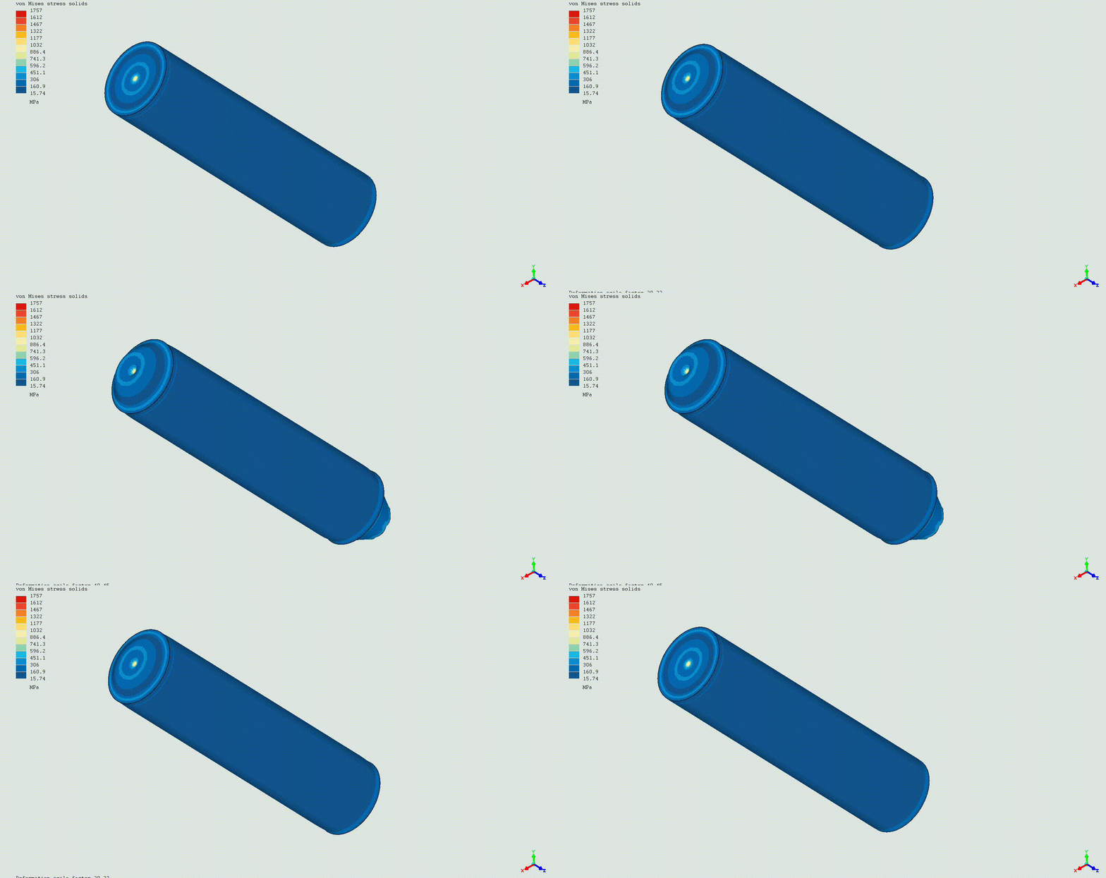
I have try it modeling a cylinder under 1MPa internal pressure with one of the ends open.
That makes an unbalance model with a Z reaction (longuitudinal axis of the cylinder ) of 994N.
The model needs a minimum constrain of one point in Z direction but that do not represent any limitation and it is also mentioned in the Abaqus procedure.
The BC requires balancing externally applied forces on a free or partially constrained body with loads derived from constant rigid body accelerations.
That is to say to introduce a gravity (force) that provides the same resultant but in the opposite direction. That way the force in the node becomes in balance.
You can see my results and how the external reaction and its peak stress on the constrained node disappear. The final reaction at the node is -0.092N compared to the initial 994N.
I guess one should proceed in the same way in case there are reaction forces in X or Y adding new components to the gravity to compensate. Curiously the model solves faster with the inertia relief.


What if the model is balanced (like a closed vessel with pressure) ? Of course apart from utilizing symmetry when possible. I’m afraid that gravity loads in 3 directions wouldn’t help in such a case and that’s the most common situation when inertia relief is used.
Apart from that, sometimes it’s enough activating NLGEOM to allow the geometry to accommodate and release the reaction force at the constrained node. To add some soft springs may help too (as you suggest).
I am doing some testing as this is an interesting topic with good potential use for me, but I am finding some strange things with gravity defined in all three directions.
I’m not sure if it’s my model, my assumptions , my BC or the solver. I’m not used flying thinghs. ![]()
I asked the question since my opinion was also that it could be computed. I am thinking of adding it to the PrePoMax. If you think about it, this must be done in all 6 degrees of freedom in general. 3 translations and 3 rotations where for rotations, you have to decide where is the rotational point. It could be the centre of gravity. But it would work only for linear elastic analyses.
If the model is balanced, there is no need for inertia relief. Or my understanding is not accurate.
Some FEA programs can’t solve models with a balanced load and no constraints. Abaqus can do it but it’s better to avoid such cases. Apparently, CalculIX can solve them too but the results indicate that the model is flying with huge displacements.
When the loads are “balanced”, you can put a constraint anywhere to stop it flying away and it will only cause a reaction force equal to the approximately zero imbalance in the load, so it won’t really affect the deformation or stress.
Exactly. Probably one should select a point from which the displacements are supposed to be measured since It will represent the 0 displacement point at the end.
I am wondering if there is some numerical procedure used while solving the system of equations which behaves as numerical damping. So that a small enough residual force will not move the mesh for an arbitrary displacement when no support is used.
The handling could be similar to *section print. There you have the quantities (forces and moments) with respect to the center of gravity and with respect to the global origin.
Anyways, computing the resulting force and moment about CG and origin would make up a nice verification feature.
If this can’t be done reliably in pre-processing, an option would be to run the model with all specified loads but with all dofs constrained and requesting the nodal forces.
Adding appropriate rotational and translational accelerations plus soft springs would render even badly supported models suitable for linear analysis (and non-linear as well).
Ansys uses soft springs at certain points of each independent body. If you want to avoid finding these bodies, soft springs could be added to all nodes, perhaps with stiffness based on element size in order not to overstiffen densly meshed regions.
The resulting forces in the soft springs could afterwards be checked against some some tolerance, e.g. by comparing the stored energy in the springs and in the model.


