Thank You Lucas. ![]() Excellent reference for further investigation.
Excellent reference for further investigation.
Very nice point I did not care enough at the beginning. I actually just made the bottom surface fixed in all global DOF and applied a rigid body constraint to the upper surface distributing a moment. When I first saw the results close enough (4% difference against the analytical calculation) to the expected values, I just assumed the BC were right.

Restraining an out plane rotation in global coordinates not in local will lead a model to be less stiff. Connecting them with rigid body and reference nodes with torsional moment seems not appropriate in this case, even it may still possible to modify. Personally, I’ll go to transform functions and coupling type distribution for model approach. So the model of boundary condition (support & load)l become similar to analytical assumptions.
to address the issue I tried to run the problem as a static nonlinear analysis after checking the static result that show high compressive stresses in the skin near the attachment with the forward spar(s) but I get the following warning and no convergence:
STEP            1

 Static analysis was selected

 Newton-Raphson iterative procedure is active

 Nonlinear geometric effects are taken into account

 Decascading the MPC's

*INFO in cascade: linear MPCs and
       nonlinear MPCs depend on each other
       common node: 3 in direction 1
So maybe this issue could be creating the ill conditioning of the eigenvalue problem. Is there a modelization modification that doesn’t lead to this dependency?

HI Juan,
I have removed the unobtainium border. I guess it has been created to add some stiffness and help to apply the Kinematic BC but from my point of view it is giving some problems.(Too stiff maybe)
It is generating local buckling on thin layers close to him with multiple Buckling modes masking the global ones.
Same as you, I have first try to fix the static to get some realistic stresses (not only displacements)
I have fix one end and keep the kinematic coupling on the tip side.
I’m not aeronautical engineer but this wing seems like a double I-beam box girder under bending ¿isn’t it?
I say this because I have “open” the different layers and there is a clear structure supporting most of the loads.
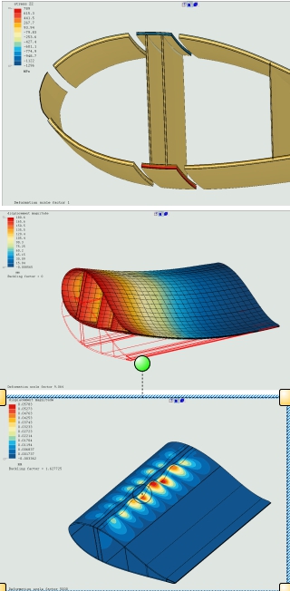
That made me suspect the Buckling load is inverted in sign.
I have changed the sign and I’m obtaining two first values very close to the lip (probably associated to the Kinematic Coupling ) and another 1.6 which is compatible with a typical Buckling mode along the double I-beam box girder.
¿Do you think the UD material parameters are right? ¿those stresses seem still high.
Uniaxial UD provided by Xyont on his reference is much more balanced when looking at the E1,E2,E3.
This model
*Material, Name=Carbon_UD
*DENSITY
1600
*ELASTIC, TYPE=ENGINEERING CONSTANTS
150.2E9,9.1E9,9.1E9,0.318,0.318,0.318,4E9,4E9
4E9,0
This model
*Material, Name=Carbon_UD
*DENSITY
1600
*ELASTIC, TYPE=ENGINEERING CONSTANTS
150.2E9,9.1E9,9.1E9,0.318,0.318,0.318,4E9,4E9
4E9,0
Compared to this.

Look correct to me. It’s carbon fiber high modulus unidirectional tape used in aerospace products. Generator blades use glass fiber as it’s cheaper. Do not know if this design correspond to a multispar wing with sandwich skins but it’s designed that way. v12 seems correct but other v’s better fit your formulas, having v >0.5 in an orthotropic material doesn’t make it incompressible.
Model is in SI units so not so high but I didn’t check closely.
Yes, composite sandwich skins thin outer faces in upper (extrados) and lower (intrados) sides and very light core in the middle, foam here to stabilize the faces in compression/shear and increase bending capability like in H beams.
I see. New product to me. E1/E2=16.4 which completely mess the B. M. LEMPRIERE criteria. What still is strange to me is that this wing seems thinner where one would think its more needed. Flange in compression and front side in case of some impact. Definetively this is not my area.

¿Have you run the Abaqus solution to see the buckling shape?. That solution is not in the core web panels as it has been shown in previous solutions. Maybe there is even a lower mode I have jump.
We do not know the degree of development of this design, almost sure you’re right in your perception, the design is in need of evolution.
this is pretty old, since the advent of carbon composites I think, but the modulus keeps going up as fiber manufacturing improves HexPly_M21_global_DataSheet.pdf (hexcel.com)
Check this!!. Just have the idea . Extending the unobtainium border further and relaxing it’s stifness solves without any other modification. That seems to confirm the Kinematic Coupling is too close and probably too stiff and interfering on the Buckling solution.
I would extend the unobtainium (or maybe the UD core to keep continuity ) with two or three layers too give enought space to the kinematic coupling to properly transfer the loads.

Availability of some references by analytical or test results also known as target values. It’s relative easy, possible the model to be improve and adjust by mesh refinement, dummy element, stiffness modification, etc. Large testing by variance of the FE model itself required to conduct to eliminate an over confidence since the models are probably not represent as is.
Today research do blind predictions, meaning the analysis model is develop and reporting before physical testing being conduct. There’s challenging since no known solution and results is available.
1 Like
Yes, I agree. It is a nice mindset to adopt whenever using FEM.
this file isn’t working for me…
I guess this is just a measure of how close/far from orthotropic are actual composite materials. Looking at your own calculations based on Lempriere I’d say that looks like decent approximation with some peculiarities.
More data:

right, looks like the coupling and/or its interaction with shell knots (the 2 distinct features that are different compared to Abaqus) are the source of the issue.
by the way…does this last modification allow to run the nonlinear static analysis?
Good contribution Disla, as usual. And thanks for the modified file.
PS: I’dsay as well that using Abaqus to check CCX models is OK, but using CCX to run Abaqus models is something to be carefully considered.
Thanks JuanP,
I haven’t try but stresses are now much more moderated. Probably yes.
I have fix the load and keep the original positive model sign and Buckling factor is similar to ABAQUS and ANSYS (1.4)
1 Like
It seems not comparable of each model i.e S6 and S8. Abaqus conventional shell element use classical formulation based on plate and membrane theory in 2D plane. CalculiX shell use continuum ones 3D by expanding to solid element, it may comparable to Abaqus continuum shell element i.e SC6R and SC8R even not exactly the same. Load and support modeling approach of convention and continuum shell also treatment differently in Abaqus itself.
