Beam elements also have surfaces. The B31 and B31R elements are expanded
into C3D8I and C3D8R elements respectively and are treated as such.

Can we define expanded surface in .inp card before we run the analysis? There is only two fixed nodes in here. How can we define expanded version of beam? I dont think the solution f the problem is that.
Isn’t there a simple answer for taking moment reactions directly from calculix? I really cannot believe it:)
I have only two beams as a reminder ı put the model again.


I think some other easy options we should have to exract moment data. @JuanP74 , @Calc_em do you have any suggestions? Isn’t there a simple answer for taking moment reactions directly from calculix? I really cannot believe it:)
I would say that all the available options are described in the post.
I think the easiest for you would be :
1-Set your model such that the beam of interest is aligned with the global coordinate system. You will avoid reference system transformations.
2 – *EL FILE, SECTION FORCES,OUTPUT=2D
S,NOE
Read the values in the .frd file
Start with a single cantilever beam to understand axis orientations.
You may try using *coupling and then asking for RF output, however the surface has to be defined as well. Check example coupling1.inp in the example files provided with CCX.
remember that ccx is a software focused on continuum elements and structural elements are built around them with clever tricks but aren’t true structural elements.
Hi,
I think I understand better @osmcnkrtn concern.
I was experimenting with different options to extract nodal moments and forces of beams with different orientations.
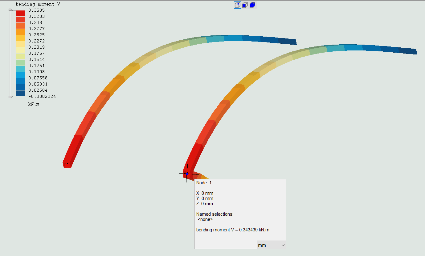
I have introduced first a dummy beam connected to one of my beams of interest at a fixed node. See picture of my configuration.
I have found that when adding a new beam to the fixed support, the forces and moments are now averaged there giving one half the original value although the node is fixed and should not transfer load from one beam to the other.
If I add an additional force to the dummy , although there is clearly an additional shear and moment arriving to the fixed node, both systems show similar results because the values are averaged.
I don’t think that is right. ¿What do you think?


1 Like

it seems section forces keyword options will work for this task, reported for every nodes including support and concentrated load positions. CalculiX shown any values for external forces and internal forces (incl. reactions)
It does not make sense. Even if the orientation cordinates differs, if ofsett values remains same, there has to be no major changes in forces. I think we make wrong by extracting outputs.