Bruno,
I have not run your model as given but maybe you should try B32R elements as opposed to B32.
Regards,
Bruno,
I have not run your model as given but maybe you should try B32R elements as opposed to B32.
Regards,
Hello Frank
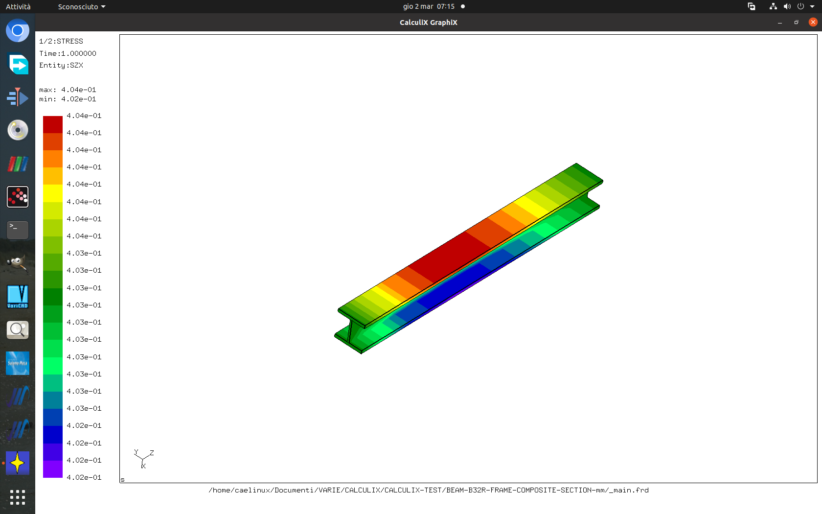
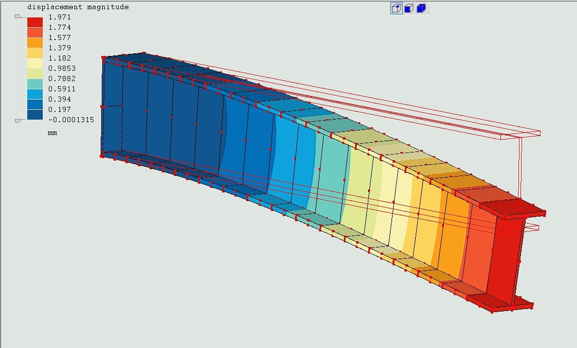
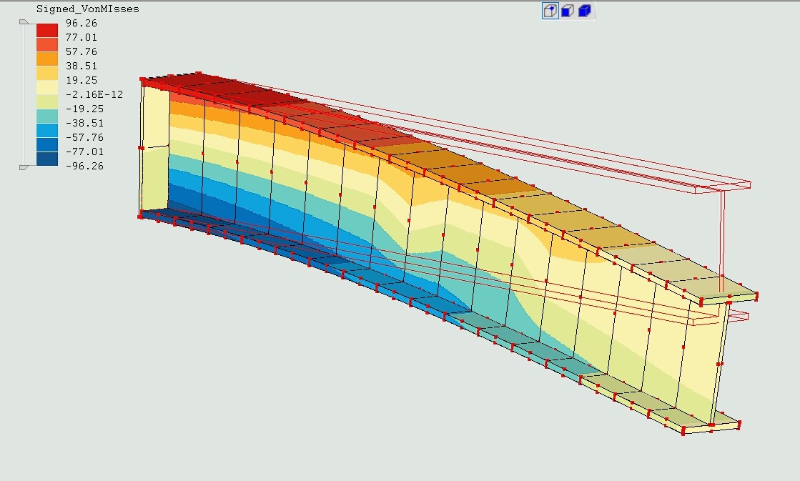
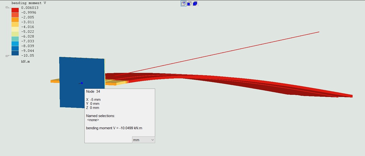
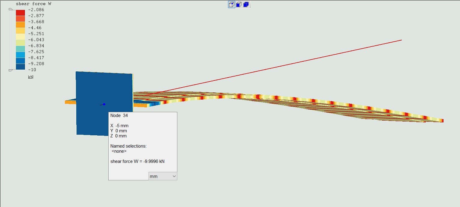
I did it, but the results are unlikely too. The displacements are in the range of a possible true, but the bending moment is unlikely.
main.inp
*node, nset=Nall
1, 0.000000e+00, 0.000000e+00, 0.000000e+00
2, 0.000000e+00, 0.000000e+00, 6.666667e+01
3, 0.000000e+00, 0.000000e+00, 3.333333e+01
4, 0.000000e+00, 0.000000e+00, 1.333333e+02
5, 0.000000e+00, 0.000000e+00, 1.000000e+02
6, 0.000000e+00, 0.000000e+00, 2.000000e+02
7, 0.000000e+00, 0.000000e+00, 1.666667e+02
8, 0.000000e+00, 0.000000e+00, 2.666667e+02
9, 0.000000e+00, 0.000000e+00, 2.333333e+02
10, 0.000000e+00, 0.000000e+00, 3.333333e+02
11, 0.000000e+00, 0.000000e+00, 3.000000e+02
12, 0.000000e+00, 0.000000e+00, 4.000000e+02
13, 0.000000e+00, 0.000000e+00, 3.666667e+02
14, 0.000000e+00, 0.000000e+00, 4.666667e+02
15, 0.000000e+00, 0.000000e+00, 4.333333e+02
16, 0.000000e+00, 0.000000e+00, 5.333333e+02
17, 0.000000e+00, 0.000000e+00, 5.000000e+02
18, 0.000000e+00, 0.000000e+00, 6.000000e+02
19, 0.000000e+00, 0.000000e+00, 5.666667e+02
20, 0.000000e+00, 0.000000e+00, 6.666667e+02
21, 0.000000e+00, 0.000000e+00, 6.333333e+02
22, 0.000000e+00, 0.000000e+00, 7.333333e+02
23, 0.000000e+00, 0.000000e+00, 7.000000e+02
24, 0.000000e+00, 0.000000e+00, 8.000000e+02
25, 0.000000e+00, 0.000000e+00, 7.666667e+02
26, 0.000000e+00, 0.000000e+00, 8.666667e+02
27, 0.000000e+00, 0.000000e+00, 8.333333e+02
28, 0.000000e+00, 0.000000e+00, 9.333333e+02
29, 0.000000e+00, 0.000000e+00, 9.000000e+02
30, 0.000000e+00, 0.000000e+00, 1.000000e+03
31, 0.000000e+00, 0.000000e+00, 9.666667e+02
*nset, nset=BC
1,
*nset, nset=LX
30,
*element, elset=B32R,type=B32R
1, 1, 3, 2,
2, 2, 5, 4,
3, 4, 7, 6,
4, 6, 9, 8,
5, 8, 11, 10,
6, 10, 13, 12,
7, 12, 15, 14,
8, 14, 17, 16,
9, 16, 19, 18,
10, 18, 21, 20,
11, 20, 23, 22,
12, 22, 25, 24,
13, 24, 27, 26,
14, 26, 29, 28,
15, 28, 31, 30,
16, 1, 3, 2,
17, 2, 5, 4,
18, 4, 7, 6,
19, 6, 9, 8,
20, 8, 11, 10,
21, 10, 13, 12,
22, 12, 15, 14,
23, 14, 17, 16,
24, 16, 19, 18,
25, 18, 21, 20,
26, 20, 23, 22,
27, 22, 25, 24,
28, 24, 27, 26,
29, 26, 29, 28,
30, 28, 31, 30,
31, 1, 3, 2,
32, 2, 5, 4,
33, 4, 7, 6,
34, 6, 9, 8,
35, 8, 11, 10,
36, 10, 13, 12,
37, 12, 15, 14,
38, 14, 17, 16,
39, 16, 19, 18,
40, 18, 21, 20,
41, 20, 23, 22,
42, 22, 25, 24,
43, 24, 27, 26,
44, 26, 29, 28,
45, 28, 31, 30,
*elset, elset=WCLM
1, 2, 3, 4, 5, 6, 7,
8, 9, 10, 11, 12, 13, 14, 15,
*elset, elset=PL1CLM
16, 17, 18, 19, 20, 21, 22,
23, 24, 25, 26, 27, 28, 29, 30,
*elset, elset=PL2CLM
31, 32, 33, 34, 35, 36, 37,
38, 39, 40, 41, 42, 43, 44, 45,
In my opinion, Juan described well the issue. The way that the B32 (and B32R) are designed is not suitable for getting out the section forces.
If the developers may decide to do a workable beam element suitable for eurocodes, I pray them warmly that It can be a great thing, to do the possibility to use the 2D mesh section in the analysis.
It can be: 1) the analysis runs with general parameters, I, A, J…; I know that. At the moment it does it, but the visualization of results is impossible with cgx. Please, for working in an industrial way, let us to visualize the results even with cgx, that is fair good, or better with vtk paraview family. I know that there is the converter, It works fair well, but it needs anyway the frd file. Why don’t go to paraview straight?
Thank you very much for your work and your kind attention to these maybe trivial questions, but close connectect to the industrial world.
Best Regards
Bruno
I think the problem could be the axis orientation. Web and Flanges have their normal axis oriented in different directions (as they must) which probably puzzles the extraction.
I have built an IPE160 of 1m with 10KN on the tip in a similar way as you and shears are wrong at the nodes. It can be solved but the extraction is averaging and mixing forces defined in different coordinate systems. Like adding apples with pears.
I have built an additional dummy element at the base of the beam in such a way that it is not composed so it has a unique axis system.
It is kind of I am measuring the shear and bending moment “at the wall” instead of the beam if that’s ok with you. I know this should be fixed but if you need it this could be a temporary solution.
It seems to work. Try it yourself in your model.
dear Disla, thank for your intrest and the temporary solution. This can be helpful; but as you know, this is not an industrial way of doing, it is just a work around, even though intresting and clever.
Anyway, thank you very much indeed, also because you pointed out that B32 needs to be fixed.
Best Regards
Bruno